VIDEO MODULATOR PRACTICE


Objectives :
1.       To measure the frequency spectrum in video transmission.
2.       To determine the space carrier frequency of picture and carrier frequency of audio.
3.       To determine the bandwidth of video transmission.
4.       To determine the kind of picture and audio modulation.
Instruments:
1.       1  Modulator video (VCD/DVD/video sender)
2.       Spectrum Analyzer
3.       Connection cable RCA-BNC
Circuit Diagram

Theory
Video modulator is a circuit which converts composite video signaland audio to an RF signal which can be connected to TV antenna input. In video modulators audio+video is modulated onto a radio frequency (VHF or UHF) carrier in the range of 30 MHz to 900 MHz. This means that using a video modulator you can fed the normal video signal you get from video out connector (RCA or BNC) to a signal which can be connected to antenna input connector (F-connector orIEC antenna connector) of another video device. Basically a video modulator is a very low power TV transmitter. Most analogue TV systems use a modulation called vestigial sideband.Vestigial sideband is an AM signal with most of one sideband filtered out to save bandwidth (all you need is the carrier and one sideband torecover the video). This is how broadcasters do this. In simple devicesit is usually easier to leave a "Vestige" of the other sideband to prevent phase shift from the filter affecting the signal quality.

The way to emit (transmit) signal of pictures that amplitude modulated similar with a radio broadcasting system that has been known. In both cases, the amplitude of a carrier wave radio frequency (RF) is made varies with the modulating voltage. Modulation is a signal of fundamental frequency (baseband). On television, this baseband signal is a composite video signal. Broadcast television is really such a radio system, but includes pictures and sound. Sound signal emitted by joining in it frequency modulation (FM) on a separate carrier wave transmitter in the same channel as the image signal.

Understanding the image signal is used here to mean a modulated carrier wave. The video signal is a signal to a picture tube. Video signal to television audio signal corresponds to the sound system. Details are clearer than the image signal AM (amplitude modulation picture) and an FM voice signal.
 
Figure 1. wave amplitude modulated composite video signal

 Figure 2. Image signal AM frequency spectrum a). Without VSB. b). With VSB

Figure 2.a shows the frequency spectrum of video transmission that produces an image signal comprising AM picture carrier frequency (center frequency) and sound carrier frequencies (frequency side of the upper and lower side frequencies) - without VSB, while Figure 2b shows the frequency spectrum in transmission generate video image signals of AM frequencies only have the upper side only (with VSB).
  

Step :
1.       Calibrate the spectrum analyzer with determine the spectrum reference.
2.       Set up the instruments like the picture above.
3.       Turn ON the instruments
4.       Determine the output of  video modulator (RF) with spectrum analyzer and see the frequency spectrum.
5.       Draw the spectrum.
6.       Determine how much the  picture carrier frequency, audio carrier frequency and difference of carrier frequency of picture and audio.
7.       See the spectrum, determine the kindof modulation that be used in that transmission with change the FREQ, SPAN (in the smallest scale)
8.       Draw the multiply frequency spectrum and frequency base.

Question
1.                   What system that be used in that video modulator ?
2.                   From the sixth step, how to know thekind of modulation ?

Result 


Answer
1.    Modulation system that be used in that video is Amplitude modulation, because the amplitude of information signal give effect  to the amplitude of carrier signal, information signal becoming a cover of carrier signal


The general using of Am signal is : to Broadcasting Am radio that many used to broadcast the radiosignal AM, TV picture (Video),  Communication radio : aeroplane, amateur radio (SSB), CB radio ( Citizen Band Radio). Digital taransmissiondata : Computer Modem (Combination with QAM modulation). 

2.   We know that the kind of modulation is amplitude modulation can be seen from the difference of  amplitude and had the AM spectrum.
From the AM formula, we know that the modulated signal spectrum AM had 3 frequencies :
·        Fc : carrier signal frequency
·      LSB : Lower Side Band Frequency, that is difference of carrier signal frequency and information signal.
·      USB : Upper Side Band Frequency, that is summary of carrier signal frequency and information signal.
 
Conclusion
1.       Video modulator use amplitude modulation
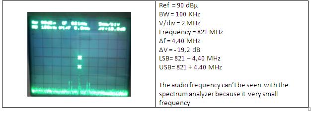
2.       AM Modulation in spectrum analyzer  show three frequencies :
·         Carrier frequency (fc)
·         Lower Side band Frequency (LSB)
·         Upper Side BandFrequency (USB)
3.       The difference between USB and LSB for about 4,40 MHz
4.       Bandwidth that be used is 100 KHz

COMPOSITE VIDEO PRACTICE

OBJECTIVES:

1.1 To know the base of composite video
1.2 To measure composite video and standart voltage
1.3 To determine the parameter of composite video


INSTRUMENTATIONS:

1 VCD/VTR
1 Oscilloscope 40 MHz and passive probe
1 Conector cable RCA - BNC (75 ohm)


CIRCUIT DIAGRAM :
THEORY :
Composite video is the most common type of video interface for sending or receiving an analog video signal to or from a television set. A composite video interface might connect a VHS tape player, DVD player or game console to a television
Composite video is a yellow, female RCA jack, normally found next to two audio jacks, one red, the other white. The three jacks together provide an interface for audiovisual connections. The red RCA jack connects the right channel of a stereo system, while the white RCA jack connects the left. The yellow composite video jack rounds out the set.
A video stream is composed of a Y signal for luminescence or black and white values and a C signal for chrominance or color. The Y signal provides brightness and contrast, allowing for deep rich blacks and startling bright whites. The quality of this signal is especially evident in low-lit scenes where a degraded signal will translate to "faded" blacks and muted whites, making it difficult to differentiate scenery or action. The color signal รข€”- or RGB for red, green and blue -- carries the information needed to create changing hues. A degraded C signal can result in coloration that is not true to its source.
Composite video is so named because the Y/C signals are compressed and channeled through a single wire to be separated by a "comb filter" inside the television set. Though composite video was the standard for many years, the very process causes some degradation of signal integrity. This wasn't a problem in the past as television resolution and audiovisual equipment in general was inferior to today's standards. However, with the advent of high-definition television and DVD, the drawbacks of composite video have become evident on screen.

Limitations of composite video led to S-Video, a mini-DIN interface that carries the Y/C signals separately, each getting their own wire wrapped inside a single sheath to appear as a single cable. S-Video is also analog and still requires audio cables. More recently, S-Video has been superseded by component video, which isolates not only the Y signal on its own cable, but the red and blue signals as well, while green values are inferred from reading the other data streams. Component video requires three cables plus audio cables, for a total of five cables. The latest enhancement in audiovisual interfaces is High-Definition Multimedia Interface (HDMI), a true digital interface that combines video and audio into a single cable while preserving perfect integrity. This all-digital standard is the most desirable interface currently available.
The composite video signal is constructed with 3 basic elements:
- Luminance Information from DC to 5.5MHz (B&W Detail)
- Chrominance Information modulated onto a carrier (at 3.58MHz or 4.43MHz)
- Synchronization Information (Horizontal and Vertical Sync)


Step :
      1.    Set up the device like inte picture above, then connect the video out VCR/VCD with CRO input.
      2.    Turn ON the instrument.
      3.    Set the CRO to get a good picture (use the switch MODE  at TV-H position but to look the vertical
           synchronization wave put the switch MODE at TV-V)
      4.    See and draw the pulses of synchronization and horizontal blanking, vertical blanking pulse, front  
           of    and back, and picture information.
      5.    Draw the shape of that wave and determine the voltage.

Question:
      1.    How much the  horizontal synchronization frequencies and vertical synchronization?
2.    What system that be used in that video?

Result

 Analyze

Answer: 
1.    The horizontal synchronization frequencies = 31,68 KHz 
     The vertical synchronization frequencies = 70,71 Hz
      2.    The system that be used in that video is the AM modulation because can be seen at the difference 
           of amplitude and have the AM spectrum.

Conclusion
      ·         A Composite Video is analog television signal's format before a sound signal is combined with it 
           and modulated onto an RF carrier.
      ·         A composite video consist of blanking signal and synchronization signal.
·         From the voltage of the signal we can determine the frequencies that be used in that video.